Introduction
In a distributed system, each entity with storage or computational resources is called a 'node', connected with each other over a network . These nodes perform different functions such as computing, storage, routing, caching, etc. based on the applications demand. There are two orthogonal type of architectures which one should know about while designing a system. This article focuses on explaining Server-Client architecture and Peer to Peer (P2P) architecture with detailed examples of both. This blog also covers load balancing and hashing technique briefly.


Working of Napster


Server Client Architecture
In this type of architecture, a node is assigned a role of either acting as a 'client' or as a 'server' in a given context. These roles are not rigid - a server may act as a client in some other context. A client generates a 'request' and passes it to appropriate server which then processes the request and returns a 'response' message for the client as shown below.

An example of a 'request' can be a HTTP request from a client's browser to access a page from a web server. The web server in this case responds with an HTML page along with other parameters. The diagram of a system shown above is naive and impractical, since there can be multiple clients and the server might get flooded with requests and may crash. Let's improve upon the model and add some more servers.

The modifications which we have done to handle multiple clients is to add more servers and also add a load balancer which distributes requests to the appropriate server. This is known as 'horizontal scaling'. This addition of more server nodes makes the system fast, responsive and reliable.
One may argue that the load balancer may itself become a 'single point of failure' (SPoF). If the load balancer crashes, our system will suffer a heavy network partition and clients' requests will not be handled. This is usually not the case because load balancers are designed in a 1+1 or a N+1 manner. One or most balancer may act as a master balancer and other may acts as back-up slave balancers. This type of redundant designing to prevent SPoF can be applied to many use-cases and 'Master-Slave' architecture is used in many modern day systems.
Load balancers can be categorized into :
- Network Load Balancers : These entities balance the requests on multiple servers based on the network load on each server. The distribution of traffic is based on network variables, such as IP addresses and destination ports. They are not designed to take into consideration anything at the application layer such as content type, cookie data, custom headers, user location, or the application behavior.
- Application Load balancers : The distribution of traffic done by these load balancers is based on the application layer data and can be configured by the system designer. These type of load balancers provide higher flexibility to system designer in the sense that one can define the rules of traffic distribution. An example can be this that the balancer distributes requests based on the location of the client, i.e. the request is passed on to the closest server.
The other difference between the two is important because network load balancing cannot assure availability of the application. This
is because it bases its decisions solely on network and TCP-layer
variables and has no awareness of the application at all. An application load balancer goes much deeper,
and is capable of determining availability based on not only a
successful HTTP GET of a particular page but also the verification that
the content is as was expected based on the input parameters.
Content Delivery Networks (CDNs) are another piece of architecture that are used to geo-distribute traffic to prevent central servers from getting overwhelmed with requests. They are a beyond current scope of discussion.
Let's build upon the architecture discussed so far and introduce the basic 'three tier model' of distributed servers :

The three tier model shown above is one of the basic ways you can think of designing a system. The tiers are explained below :
- Presentation Tier - front end part of the application interacting with the user. Nowadays, more and more functionality is being shifted to the front-end portion with efficiency using hundreds of javascript frameworks available at present (no offence! they all are awesome!).
- Business Logic Tier - the collection of back-end servers running in a cloud environment with load balancer distributing traffic judiciously. Back-end frameworks such as Django and Node.js can be used for coding such servers.
- Database Tier - The back-end servers perform operations on database. Since traditional databases are SPoF, we need distributed versions of databases. We can 'shard' (divide) the data among multiple nodes and replicate it at multiple nodes to make it efficient and fault tolerant. A good example of such a distributed database is a Cassandra virtual ring which provides high availability as well as eventual consistency. I will soon write a separate blog on the Cassandra architecture and working, so stay tuned!!
I hope you have gained a fair idea of how to design a scalable architecture using servers. Implementing these architectures is itself a challenging task. Nodes keep crashing, data and cache entries may become inconsistent, the network may drop packets, the 'Master' node may crash, leading to a reelection among remaining nodes, and so on and so forth. Each of the issues will be covered in future blog posts , subscribe to the blog and keep reading!!
Let's move our discussion to an orthogonal architecture - P2P systems.
Peer to Peer Architecture
This architecture also consists of nodes connected to each other over links, but all of them are 'peers'. Unlike the client-server model, in which the client makes a service request and the server fulfills the request, the P2P network model allows each node to function as both a client and a server. Peer-to-peer applications allow users to control many parameters of
operation: how many member connections to seek or allow at one time,whose systems to connect to or avoid, what services to offer, and how
many system resources to devote to the network.
The main advantage of a P2P system over Server-client systems is that it is decentralized, i.e. there is no one central governing authority and hence it is more dynamic and flexible. On the other hand, P2P systems are less stable, since all the resources (music files, videos, documents) are contributed by various peers and if any of the peer is down, the files owned by it will become inaccessible. For more detailed comparison , visit this link.
Let's understand P2P systems with some examples. Napster was a set of three music-focused online services. It was
founded in 1999 as a pioneering peer-to-peer file sharing Internet
software. It is not strictly peer-to-peer as will be shown below :

Working of Napster
The Napster system consists of two entities - Peers and Napster Servers. All the music files are stored at the peers. When a new peer joins the system, it discovers a Napster server via a DNS query and estabilishes connection. The Napster servers themselves do not store files, instead they store 'file_Id -> Peer Pointer(IP address)' mapping. When a peer generates a request for a file, the connected Napster server searches it's own list for that file id and also queries other servers in case it does not find an entry in it's own list. Once the IP address of the peer containing the file is found, it is sent to the requesting peer which then can initiate a file transfer. The napster servers are themselves not involved in file transfers.
Napster suffered lawsuits on elegations of 'promoting piracy' and was eventually shut down.
But this is not a truely P2P system. Let's take an example of Chord, which uses DHT(distributed hash tables) to optimize query of a file. I assume you know what 'hashing' is and if not, you can learn about basics of hashing and hash tables here. DHT are just normal hash tables in a distributed environment.
Chord addresses the issues of latency, fault tolerance and load balancing. It provides lookup time, latency and number of messages for lookup all of the order of O(log N) where N is the number of peers. Let's see in details.
Setup and Working of Chord

Setup and Working of Chord
All the peers/nodes in a chord system are arranged in the form of a virtual ring as shown above. The ring has points on it from 0 to 127 (just for the example, m may vary as per the scenario). Each node's id(IP address or some other unique identity) is hashed using a hash function (modulus operation in above example) and the node is given a position on the ring based on it's hashed value. Thus a node with Id 160 when hashed with a modulus operation gets a position of 32 (160 mod 128) on the ring (represented as N32).
Each node has two type of neighbours (whose adressess it stores) from which it is connected :
- Successors : the node at the next position in the ring clockwise. Hence N45 is connected to N80, N112 is connected to N12 and so on.
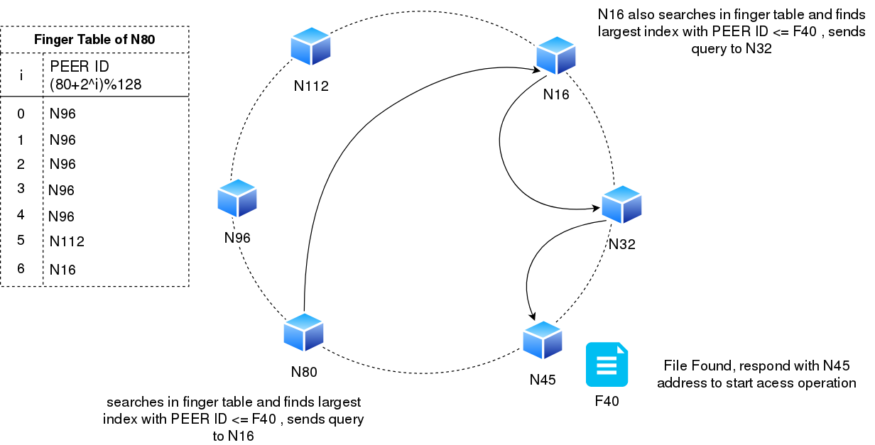
- Finger Table Entries : each node 'Nj' maintains a finger table. 'ith' entry of the finger table stores peer id >= (Nj + 2^i)%m (0<= i < M). An example of all the neighbours of node N80 is shown below.

In chord, the files are also hashed (file IDs are hashed) and they are stored at the node with peer id >= hash(file id)%m(nearest clockwise node). So, if a file's hash value is say 40(represented by F40), it will be stored at N45.
Now Let's take an example where N80 node requires access to file with 'Key F40'. Its does not know at which node the file is stored. How N80 queries for a file is described below :
- Node N80 sends the query to the largest finger table entry which is less than or equal to file key F40. We can see that N16 is the largest finger table entry (largest in terms of index) which has ID < F40 (16<40). If no such finger table entry exists, N80 would have sent query to it's successor.
- Node N16 on receiving a query from N80 repeats the above step. The full cycle of file discovery and fetch is shown below.
Additional features of Chord P2P system :
- File Replication : What will happen if node N45 crashes for some time. This means that file F40 will be inaccessible or may be completely lost if the node never recovers. To prevent this, files are replication at 'k' number of successors of a node. Hence F40 file may be replicated at N80. Caching is also be used by all the nodes to reduce latency. But file replication consumes storage. Nodes may also store just the meta information (location and id) of a file in cache instead of the whole file.
- Optimal Query time and traffic : As the distance of finger table entries increases exponentially, It may be suffice to say that at each query iteration, the search space of the query gets reduced to half of the current ring(see the diagram above). Hence, the query complexity is O(log N), N being the number of nodes.
- Rate of Churning : Churning implies a dynamic system, a system where peers fail, new peers join, old peers leave. Each node hence needs to update its successors and finger table entries periodically. High rate of churning may cause the ring to become disconnected. Hence, each node runs a stabilization protocol which tries to keep up with the rate of churning. When a new node enters the chord ring system, it knows about only those nodes that it's successor knows about, hence the stabilization protocol is run periodically by all the nodes to discover new nodes in the system, detect failed nodes in the system, and update their finger tables and successors.
Conclusion
We discussed two form of system design architectures - Server Client and P2P. and briefly covered the 'three tier model' and 'Chord system'. Some topics like CDNs, load balancing, Cassandra distributed database, Master re-election and Node failure detection protocols have been abstracted to a large extent to maintain the brevity of the blog post. I will soon write detailed blogs on these topics also. Things which one would appreciate from the design shown above include the scalability offered through redundancy and the use of hash tables and virtual ring to create an effective P2P system.
Do comment your views, queries and feedbacks on the content of the blog post. It will be highly appreciated !! Cheers!
Comments
Post a Comment